Measurement is the initial phase of working with a new project. It involves not only noting all necessary dimensions on the floor plan but also thoroughly inspecting the space, photographing the entire volume and individual elements, understanding the structural characteristics of the building housing the space, and documenting every detail that could influence the interior design development and subsequent planning. A measurement plan is an accurate drawing of all rooms within the project, documenting their actual dimensions, all projections, columns, beams, openings, podiums, niches, and their heights, as well as the engineering utilities (heating, ventilation/air conditioning, plumbing/sewerage, electrical systems, etc.).
GENERAL GUIDELINES
It is best to take measurements during daylight hours, with sufficient natural light. Having a portable light source is helpful for inspecting utility closets, recesses, and areas that are away from the main lighting. If the developer provides a floor plan, or a BTI* plan (you can even use an evacuation plan as a base in some cases)—make sure to print and bring these to your measurement session; this will simplify and speed up the process. *The BTI plan does not contain complete information about the space. The maximum detail it provides is the area, the location of wet areas, and the main dimensions, which can vary significantly from the actual layout.
If a floor plan is unavailable, sketch a rough layout of the rooms. If there are many rooms, you can create a general scheme of room placement, number them, and then take measurements for each numbered space on separate sheets. Also, don’t forget to sketch the window and door openings and their operating methods—this is especially crucial if the windows will not be changed, or if the «unified facade appearance» cannot be altered.
When starting to measure each room, the first step is to measure its overall dimensions: the total length and width. Next, establish «measurement chains.» Remember to periodically check whether the sum of the «measurement chains» matches the overall dimension. Verify the width and length of the room in several places, as wall corners may not be 90 degrees, and dimensions at the beginning and end of the room may differ. The walls themselves may also have a «sail-like» geometry.
After recording all dimensions on the plans, be sure to measure the ceiling heights in each room, as well as beams, rafters, recesses, windows/doors/sills/lintels over openings, and other elements. To denote details lying on the wall surface (such as pipe and electrical runs or window placement), it is useful to create «croquis» sketches—quick drawings of wall elevations onto which the measurements are then applied. Don’t forget to determine the orientation (North-South) of the main spaces.
FOR MEASUREMENTS, YOU WILL NEED:
Printed plans (A4 format, preferably several copies)
Notebook/tablet with A4 sheets, several pencils, and pens
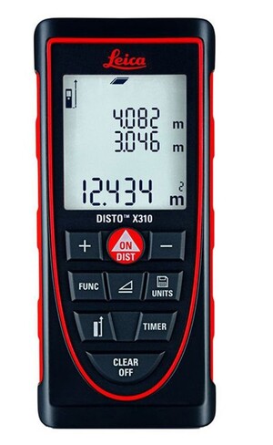
Standard and laser measuring tape with an extra battery pack

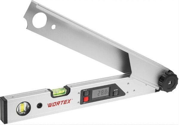
Corner measuring tool and laser level—for checking wall verticality and measuring room angles

— STANDARD TAPE MEASURE (preferably 10 m; pay attention to the tape width—the wider it is, the larger the height measurements you can take without the tape creasing) — LASER MEASURE (distance finder) with an extra set of batteries (when purchasing this tool, pay attention to the following features: Range: For large spaces and outdoor use, 50–100 meters or more. Accuracy: The standard error for household instruments is 1.5–3 mm—the lower, the better. Reference Points and Hook: The tape measure must have a folding hook (support). This is necessary to accurately measure distances from room corners. Features: Basic models can only measure length. Useful options include automatic area and volume calculation, addition/subtraction of results, and memory for the last measurements. Body Protection: For construction work, choose a protection class of no less than IP54 with rubber inserts).— Several copies of the ROOM PLAN (if available) — NOTEBOOK/TABLET or a sturdy folder with A4 sheets — PENCILS of various hardness, eraser, and pens. — Smartphone for taking photos and videos — THE PLUMB LINE—if available, but using the «diagonal method» is better and more reliable. — LASER LEVEL—helps check the verticality of walls, as well as all necessary height levels and their variations in different rooms. — LIGHT SOURCE (flashlight) — Warm clothing, if measurements will be taken on a construction site
SEQUENCE OF MEASUREMENTS:
Start the process from the general to the specific—first, the overall room configuration, then the overall dimensions, followed by the dimension «chains» for individual elements, and finally, measurements and schematic sketches of specific components.
- Sketch the object’s layout before taking any measurements. If there are many rooms, create a «scroll bar"—a diagram indicating all rooms and their labels. 2. On separate sheets, draw a detailed plan for each room corresponding to its label. Record all measurements in millimeters to avoid confusion. Verify the control sums: the sum of the lengths of individual wall sections in the «dimension chains» must equal the total length of the entire wall:
— mark the overall dimensions — verify the room for right angles using the diagonal method — measure and plot all protrusions, columns, beams, podiums, niches, openings, windows/doors. — plot the depth dimensions of window/door jambs, and the thickness of walls/partitions — ceiling heights, beam heights, heights of door and window openings, niches, and threshold heights. — indicate the boundary of the wet area in the kitchen and bathroom/toilet if they are not enclosed by walls (dimensions can be marked with paint, waterproofing, or level blocks) — measure and map all utilities: radiators, heating pipes, drainage and sewage pipes, ventilation shafts and ducts, as well as the location of the electrical panel.
Create sketches of wall elevations, marking the location of outlets, windows (with opening and glazing diagrams), and other elements.
Separately identify and measure load-bearing walls and elements (piers, columns, monolithic wall sections, arrangement of beam structures, etc.).
Document all rooms with photographs and record a walkthrough video.
SPACE ELEMENTS REQUIRING CLARIFICATION
WINDOWS: Window dimensions, jamb depth, dimensions from floor to windowsill, from windowsill to ceiling, height of the lintel/header, and sash/transom dimensions. Specify the window opening type.BALCONY/LOUNGE/TERRACE DIMENSIONS FINISHINGS: Location and type of existing finishing materials, their structure/composition—since they vary in thickness, and if the finish is removed, it may alter the ceiling height and room dimensions.ENGINEERING UTILITIES: Location of sewage and water supply risers (provide reference points for the center of the riser/pipes and specify their diameters), locations for running cold (CWS) and hot (HWS) water supply pipes, and gas pipes, referencing the walls. Dimensions of the manifold cabinet and the distance from the wall (if a manifold system is present). Locations for installing meters (heating, CWS, HWS) with height from the floor and referencing points. Location of ventilation openings and radiator size and placement.ELECTRICAL AND LOW-VOLTAGE SYSTEMS: Location of electrical outlets, placement of the electrical panel (its dimensions, height from the floor to the bottom edge, and distance from the nearest wall), and the location for the intercom cable exit.
DOOR DIMENSIONS (Example)
PHOTOGRAPHY
— Photographs of every space should be taken from multiple angles. It is preferable to photograph each wall frontally, indicating the location of the cameras on the plan of the respective room and labeling each photographed frame (e.g., Room No. ___, Wall ___,). — It is also advisable to video tour the entire facility, preferably in a walk-through format through the rooms, with an explanation of the location and corresponding labeling of each space. — It is recommended to maintain the same directional flow when taking measurements, creating photographic documentation, and conducting the video walk-through. This will simplify the association between the floor plans and the visual sequence.
MEASURING COMPLEX ROOM GEOMETRIES, BAY WINDOWS, COLUMN ALIGNMENT, ETC. USING THE DIAGONAL METHOD
Measuring rooms using the diagonal method (or triangulation method) is the most accurate way to manually measure a space with irregular geometry, non-right angles (greater or less than 90 degrees), or curved walls. The method is based on a simple geometric principle: a triangle with known lengths for its three sides has only one unique shape and area. By dividing the room into triangles, you can recreate its exact blueprint on a computer or on paper.
MEASUREMENT PROCEDURE SEQUENCE:
1. Sketch a rough floor plan of the room on a sheet of paper. Don’t aim for perfection; the main goal is to show all corners, protrusions, and niches. Assign a letter (A, B, C, D…) to each corner in a clockwise direction. 2. Use a tape measure to record the length of all walls around the perimeter (A–B, B–C, C–D, D–A). It is best to take measurements at a consistent height (e.g., at floor level or 1–1.5 meters high), keeping the tape pulled taut and flat, without any sagging. Note the measurements on the diagram next to the corresponding walls. 3. On the diagram, draw lines from one corner to the opposite corners to divide the quadrilateral (or polygon) into individual triangles. For a standard four-cornered room, drawing one diagonal (e.g., from A to C) is sufficient, but for self-checking, it is better to measure both diagonals (A–C and B–D). If the room has five, six, or more corners, select one «base» corner and draw lines from it to all other corners, excluding adjacent ones.
STEP-BY-STEP MAPPING OF AN ERKER WINDOW USING THE TRIANGULATION METHOD WITH COLUMN ANGLE REFERENCE
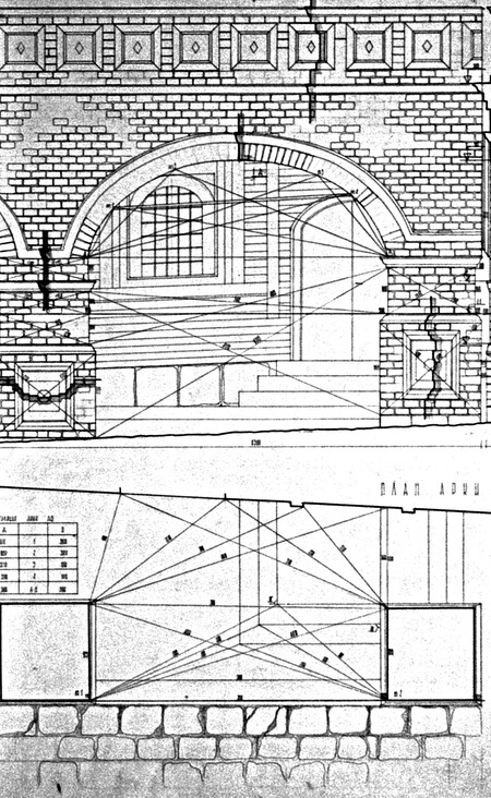
EXAMPLES OF ARCHITECTURAL MEASUREMENT SCHEMATICS FOR INTERIORS OF HISTORICAL BUILDINGS